Studying the dynamics of the rotational mechanics and ubiquitous frictional loss.
Description
The purpose of this experiment is to get familiarized with rotational motion. We normally deal with linear motion in our introductory physics class. Rotational motion is only glossed over, leaving holes in our students’ understanding. This simple experiment looks at how a torque produces angular acceleration. The moment of inertia determines how much an object can accelerate in response to torque. Angular acceleration is the change in angular velocity in unit time. How could we measure these quantities? Finally, just as in linear motion, there is ubiquitous friction which results in loss of energy. What factors determine the amount of friction?
Overview
- Dynamics of rotational mechanics.
- Linear velocity, angular velocity, and the moment of inertia.
- Frictional loss in rotational mechanics.
- Observe how torque produces angular acceleration.
- Hands-on practice with photogate and Physlogger.
- Graphical depiction for differentiation and integration.
How does it work?
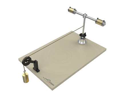
By measuring the angular velocity ω of the assembly, the experiment aims to understand how in rotation, the motion is affected by frictional torque. A vertically falling mass is used to apply a known torque on the axle, thereby rotating the horizontal shafts and a circular disc attached to it. The mass is connected to a string and is hanged freely over a pully, while the other end of the string is firmly attached to the axle.
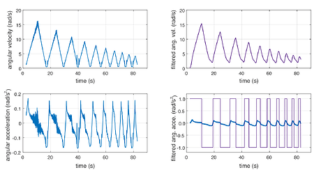
Initially, the string is wrapped around the axle to bring the hanging mass to its highest position. When released, the mass descends while rotating the axle. On reaching its lowermost position, the mass bounces up again, this time wrapping the thread in the opposite direction. In this manner, several wrapping unwrapping cycles are observed before the mass comes to rest at its lowest position. This bouncing of the mass is measured, and the energy lost per bounce and energy lost per single revolution of the axle is determined.
The disc rotating with the axle has a series of equidistant and identical spokes. These spokes intervene in the sensitive area of a photogate, creating a signal that is fed into the computer and analyzed. Using the quantities obtained from the data, the horizontal displacement of the mass and the revolutions of the axles are found. These are then used to correlate the energy lost to the angular velocity. The rotational plot based on the readings recorded is displayed.
Parts Included
- Rotating assembly
- Extra masses for the rotating rod
- Wooden base
- Pully
- Slotted weights
- String
- PhysLogger
- Photogate
>You can get the PDF version of the brochure by clicking on this link.

